Understanding Ethernet Cable Color Coding
Understanding Ethernet cable color codes is crucial for proper network installation and troubleshooting. Standardized color codes‚ like TIA/EIA 568A and 568B‚ ensure consistent wiring‚ simplifying network maintenance and repairs. Numerous online resources offer detailed diagrams and explanations.
Introduction to LAN Cable Color Codes
Local Area Network (LAN) cables‚ commonly used for Ethernet connections‚ employ a standardized color-coding system. This system isn’t arbitrary; it’s a critical aspect of ensuring reliable network functionality. The most prevalent standards are TIA/EIA 568A and 568B‚ each specifying a unique arrangement of eight colored wires within the cable. These wires are organized into four twisted pairs‚ with each pair consisting of a solid color and a white-with-color stripe. Understanding this color code is fundamental for technicians involved in network cabling‚ allowing for quick identification of individual wires and preventing common wiring errors. Incorrect wiring can lead to connectivity issues‚ impacting network performance and potentially requiring costly troubleshooting and repairs. The consistent use of these standards ensures interoperability between different network devices and simplifies the process of installing and maintaining network infrastructure. Properly understanding and applying these color codes is a cornerstone of successful network administration.
The Importance of Standardized Color Codes
Standardized color codes in LAN cables are not merely a convention; they are essential for efficient and reliable network operation. These standards‚ primarily TIA/EIA 568A and 568B‚ provide a universal language for network technicians worldwide. Without consistent color-coding‚ troubleshooting and maintenance would become significantly more complex and time-consuming. Imagine trying to identify the function of each wire without a pre-defined color scheme—a daunting task‚ especially in large or intricate networks. Standardization ensures that anyone working on the network‚ regardless of their background or location‚ can quickly understand the cable’s wiring. This simplifies repairs‚ upgrades‚ and expansions‚ saving both time and resources. Furthermore‚ standardized color-coding minimizes errors during cable termination and installation. Inconsistent wiring can lead to connectivity problems‚ network outages‚ and data loss‚ all of which can have serious consequences for businesses and organizations. The use of these standards promotes interoperability‚ facilitating seamless connections between various network devices and manufacturers.
TIA/EIA 568A and 568B Standards
The TIA/EIA 568A and 568B standards are the most widely recognized specifications for Ethernet cable color-coding. Both define the arrangement of the eight wires within a standard twisted-pair cable‚ using color-coded pairs to represent specific data transmission functions. While functionally equivalent‚ they differ in the arrangement of the orange and green wire pairs. 568A places the orange pair at pins 1 and 2 and the green pair at pins 3 and 6‚ while 568B reverses this‚ placing the green pair at pins 1 and 2 and the orange pair at pins 3 and 6. The choice between 568A and 568B is largely a matter of regional preference or organizational consistency; one is not inherently superior to the other. Maintaining consistency within a single network is key to avoid connectivity issues. Numerous online resources provide detailed pinout diagrams illustrating the color sequence for each standard‚ aiding in correct cable termination. Understanding these standards is crucial for anyone involved in network installation‚ maintenance‚ or troubleshooting.
T568A and T568B⁚ A Detailed Comparison
This section provides a detailed comparison of the T568A and T568B wiring standards‚ highlighting their differences and similarities in terms of pinouts and color codes. Choosing the right standard depends on regional conventions and existing infrastructure.
Pinout Diagrams for T568A
The T568A standard‚ while less prevalent in the US‚ maintains significant global use. Its pinout diagram showcases a specific arrangement of the eight colored wires within the RJ45 connector. Understanding this arrangement is key to correctly terminating cables according to this standard. Pin 1⁚ White/Orange; Pin 2⁚ Orange; Pin 3⁚ White/Green; Pin 4⁚ Blue; Pin 5⁚ White/Blue; Pin 6⁚ Green; Pin 7⁚ White/Brown; Pin 8⁚ Brown. This precise order ensures proper signal transmission across the network. Improper wiring can lead to connectivity issues or complete network failure. Referencing a clear‚ visual pinout diagram is crucial for accurate cable termination. Always double-check your work to avoid costly mistakes. Many online resources provide detailed diagrams and guides for various cable types. Accurate wiring is essential for reliable network performance.
Pinout Diagrams for T568B
The T568B standard is the dominant wiring scheme in North America and many other regions. Its pinout diagram differs slightly from T568A‚ affecting the order of the orange and green wire pairs. This seemingly small difference is critical for proper network functionality. The T568B arrangement is as follows⁚ Pin 1⁚ Orange/White; Pin 2⁚ Orange; Pin 3⁚ Green/White; Pin 4⁚ Blue; Pin 5⁚ Blue/White; Pin 6⁚ Green; Pin 7⁚ Brown/White; Pin 8⁚ Brown. Visual aids‚ such as pinout diagrams‚ are indispensable when creating cables following the T568B standard. These diagrams clearly show the correct wire placement within the RJ45 connector. Incorrect wiring can lead to connectivity problems‚ data loss‚ or complete network failure‚ highlighting the importance of accuracy. Numerous online resources offer clear‚ printable diagrams for easy reference. Always verify your wiring against a reputable diagram to ensure correct termination.
Choosing Between T568A and T568B
The choice between T568A and T568B wiring standards for Ethernet cables is often a matter of regional preference and existing infrastructure. While both standards achieve the same electrical result‚ T568B enjoys wider adoption in North America‚ while T568A is more common in Europe and certain other parts of the world. There’s no inherent superiority of one over the other; the key is consistency. Using a single standard throughout a network greatly simplifies troubleshooting and maintenance. Before beginning a new cabling project‚ it’s advisable to check pre-existing installations to determine the current standard in use to maintain uniformity. Mixing standards can lead to connectivity issues‚ necessitating careful planning and adherence to a chosen method. Online resources provide further details on regional prevalence and best practices for selecting the appropriate standard to ensure seamless network operation.
Creating Straight-Through and Crossover Cables
This section details the wiring procedures for both straight-through and crossover Ethernet cables‚ emphasizing the importance of consistent color-coding adherence to either the T568A or T568B standard for reliable network connectivity.
Wiring a Straight-Through Cable
A straight-through cable connects similar network devices‚ such as a computer to a switch or router. Both ends are wired identically‚ following either the T568A or T568B standard. Consistency is key; choose one standard and stick to it for both ends. Begin by stripping the cable’s outer sheath‚ exposing the eight individual wires. Carefully untwist each wire pair only as much as necessary for termination. Arrange the wires according to your chosen standard (T568A or T568B)‚ ensuring the correct color order. Insert the wires into the RJ45 connector‚ making sure they’re fully seated and straight. Crimp the connector firmly using a crimping tool to create a secure connection. Test the cable’s connectivity using a cable tester to verify proper wiring before installation. Remember‚ improper wiring can lead to network connectivity issues. Using a consistent standard across your network greatly simplifies troubleshooting and maintenance.
Wiring a Crossover Cable
A crossover cable directly connects two similar network devices‚ such as two computers or two switches‚ without needing a hub or switch. Unlike straight-through cables‚ a crossover cable uses different wiring schemes on each end. A common method involves using the T568A standard on one end and the T568B standard on the other. This effectively reverses the transmit and receive pairs‚ enabling communication. Begin by preparing the cable as you would for a straight-through cable⁚ strip the outer sheath‚ carefully untwist the wire pairs‚ and arrange them according to the chosen standards. One end follows T568A‚ and the other end follows T568B‚ ensuring the correct color sequence for each. Insert the wires into the RJ45 connectors‚ ensuring they are fully seated and straight. Crimp the connectors securely using a crimping tool. Test the cable’s connectivity using a cable tester to confirm proper wiring before use. Note that crossover cables are less commonly needed with modern networking equipment that auto-negotiates connection types.
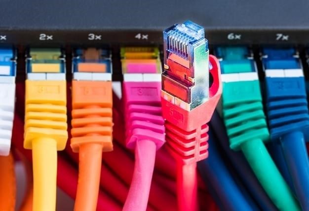
Identifying Cable Types
Accurately identifying Ethernet cable types is crucial for efficient network maintenance and troubleshooting. While color coding provides a visual guide‚ it’s not always sufficient for definitive identification. A cable tester is the most reliable method. These testers send signals through the cable and analyze the results‚ indicating whether the wiring is correct and identifying the cable type (straight-through or crossover). Visually inspecting the cable’s ends can offer clues; a straight-through cable will have identical wiring on both ends (either T568A or T568B)‚ whereas a crossover cable displays different wiring schemes. The cable’s physical characteristics‚ such as the outer jacket color or markings‚ might also provide hints‚ though this is less reliable than testing. Always prioritize testing for accurate identification‚ especially in complex network environments where multiple cable types might be used. This precise identification prevents misconnections and ensures network stability.
Troubleshooting and Common Issues
Incorrect wiring is a frequent cause of network connectivity problems. Using a cable tester helps diagnose faulty wiring and identify the specific issues. Consult online resources for visual guides and detailed troubleshooting steps.
Common Mistakes in Cable Wiring
One common mistake is incorrect wire pairing according to the T568A or T568B standards. Mixing up the color order‚ even slightly‚ can lead to connectivity issues. Another frequent error involves improper crimping of the RJ45 connector‚ resulting in loose connections or broken wires. Untwisting the wire pairs too far before crimping weakens the cable and reduces signal quality. Failure to properly seat the wires in the connector before crimping is a common cause of intermittent connections or complete failure. Forgetting to trim excess wire length before crimping can also cause problems. Additionally‚ using the wrong type of cable for the application—for instance‚ using a Cat5 cable where a Cat6 is needed—can lead to signal degradation and performance issues. Furthermore‚ neglecting to test the cable after termination is a serious oversight‚ as it leaves the possibility of hidden faults undetected until problems arise in the network. Finally‚ reusing old or damaged cables without inspecting them thoroughly for breaks or other damage can introduce unforeseen connectivity problems. Careful attention to detail throughout the entire process is essential for reliable Ethernet connectivity.
Testing Cable Connectivity
Verifying proper Ethernet cable termination and connectivity is crucial. Several methods exist‚ ranging from simple visual inspections to sophisticated network testing tools. A visual inspection checks for obvious flaws like bent pins‚ loose wires‚ or incorrect color coding. A basic continuity tester confirms electrical connection between the cable ends. More advanced tools like cable certifiers measure signal attenuation and other parameters to ensure the cable meets specifications for speed and distance. These certifiers provide detailed reports indicating potential problems like shorts‚ opens‚ or crosstalk. Network testers often incorporate features to identify cable length and wiring standards (T568A or T568B). Software-based network diagnostic tools analyze network performance to pinpoint connectivity issues related to cabling. While simple tests can catch gross errors‚ comprehensive testing with specialized equipment is vital for mission-critical networks requiring high reliability and speed. Remember‚ a properly tested cable is the foundation of a robust network.
Resolving Connectivity Problems
Troubleshooting network connectivity issues often begins with examining the cabling. Incorrect color coding during termination is a common culprit. Carefully compare the wiring to the appropriate T568A or T568B standard. Use a cable tester to pinpoint shorts‚ opens‚ or other faults. If the problem lies within the cable itself‚ replacement is usually necessary. Ensure proper crimping of RJ45 connectors; loose or damaged connectors frequently interrupt network signals. Check for bent or broken pins within the connectors‚ which can easily disrupt connectivity. If multiple cables are involved‚ test each individually to isolate the faulty one. Inspect the patch panels and network jacks for any physical damage or loose connections. If the problem persists after checking the cables‚ investigate other network components. This might include routers‚ switches‚ or network interface cards (NICs). Using a network diagnostic tool can help isolate the problem to a specific device or segment of the network. Remember to document all troubleshooting steps for future reference.
Beyond the Basics⁚ Advanced Color Coding
Beyond basic T568A/B‚ fiber optic cables and large network installations employ more complex color-coding schemes for efficient identification and management. Specialized color codes help in troubleshooting and maintenance of complex systems.
Color Coding for Different Cable Types
While the TIA/EIA 568A and 568B standards primarily govern copper Ethernet cables‚ color coding extends to other cable types. Fiber optic cables‚ for instance‚ often use different color-coded jackets to distinguish between different fiber types (single-mode vs. multi-mode) or functionalities (transmit vs. receive). Coaxial cables‚ used in older network setups or specific applications‚ might also have color-coding conventions‚ though these are less standardized than Ethernet cable schemes. Understanding these variations is crucial‚ especially when working with diverse network infrastructures or legacy systems. The specific color codes for these cable types may vary by manufacturer or application‚ so always refer to the manufacturer’s documentation for precise details. Proper identification helps in avoiding connectivity issues and ensures efficient troubleshooting.
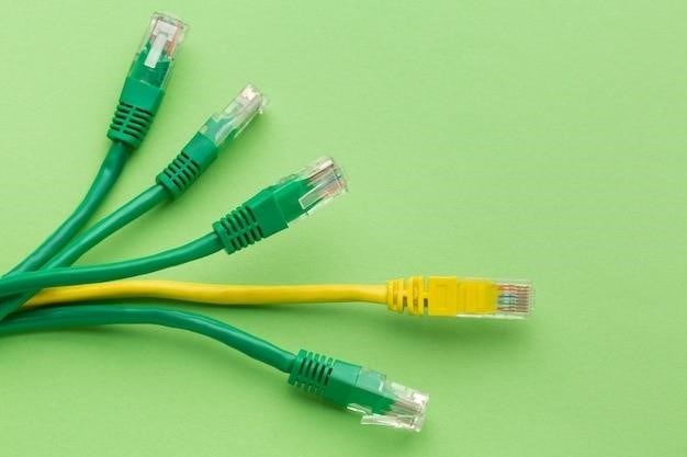
Color Coding in Large Networks
In expansive network environments‚ consistent and logical color coding becomes paramount for efficient cable management and troubleshooting. Beyond the standard TIA/EIA 568A and 568B color codes for individual cable pairs‚ larger networks often employ additional color-coding systems for entire cable runs or bundles. This might involve using different colored cable jackets to identify specific network segments‚ departments‚ or building areas. For instance‚ blue jackets might denote the main backbone cabling‚ while green jackets signify connections to specific server rooms. Such a system simplifies tracing cables‚ identifying faulty segments‚ and performing maintenance or upgrades. Detailed documentation of the network’s color-coding scheme is essential for anyone working on the infrastructure. This ensures that technicians can quickly and accurately identify the purpose and location of each cable‚ minimizing downtime and streamlining network operations. Without a well-defined system‚ large-scale network management becomes significantly more complex and time-consuming.